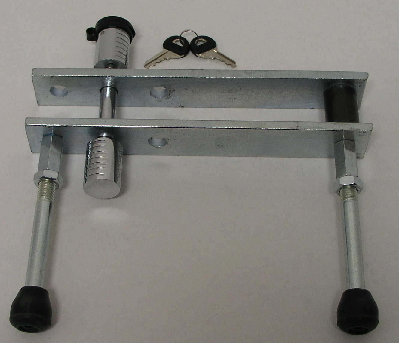
 The revised Secure Clutch and Brake Pedal Lock shown assembled. In this image you will find
all of the components necessary for installation.
The revised Secure Clutch and Brake Pedal Lock shown assembled. In this image you will find
all of the components necessary for installation.Secure Clutch & Brake Lock Images
Click on the thumbnail to view the larger image
The revised Secure Clutch and Brake Pedal Lock shown assembled. In this image you will find
all of the components necessary for installation.
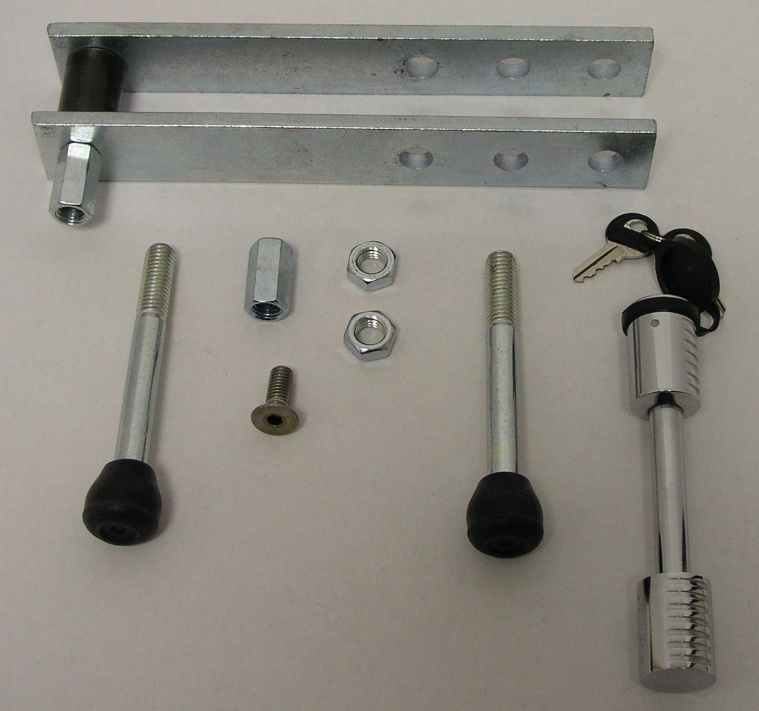 Secure Clutch and Brake Pedal Lock pictured here all with components and
unassembled.
Secure Clutch and Brake Pedal Lock pictured here all with components and
unassembled.
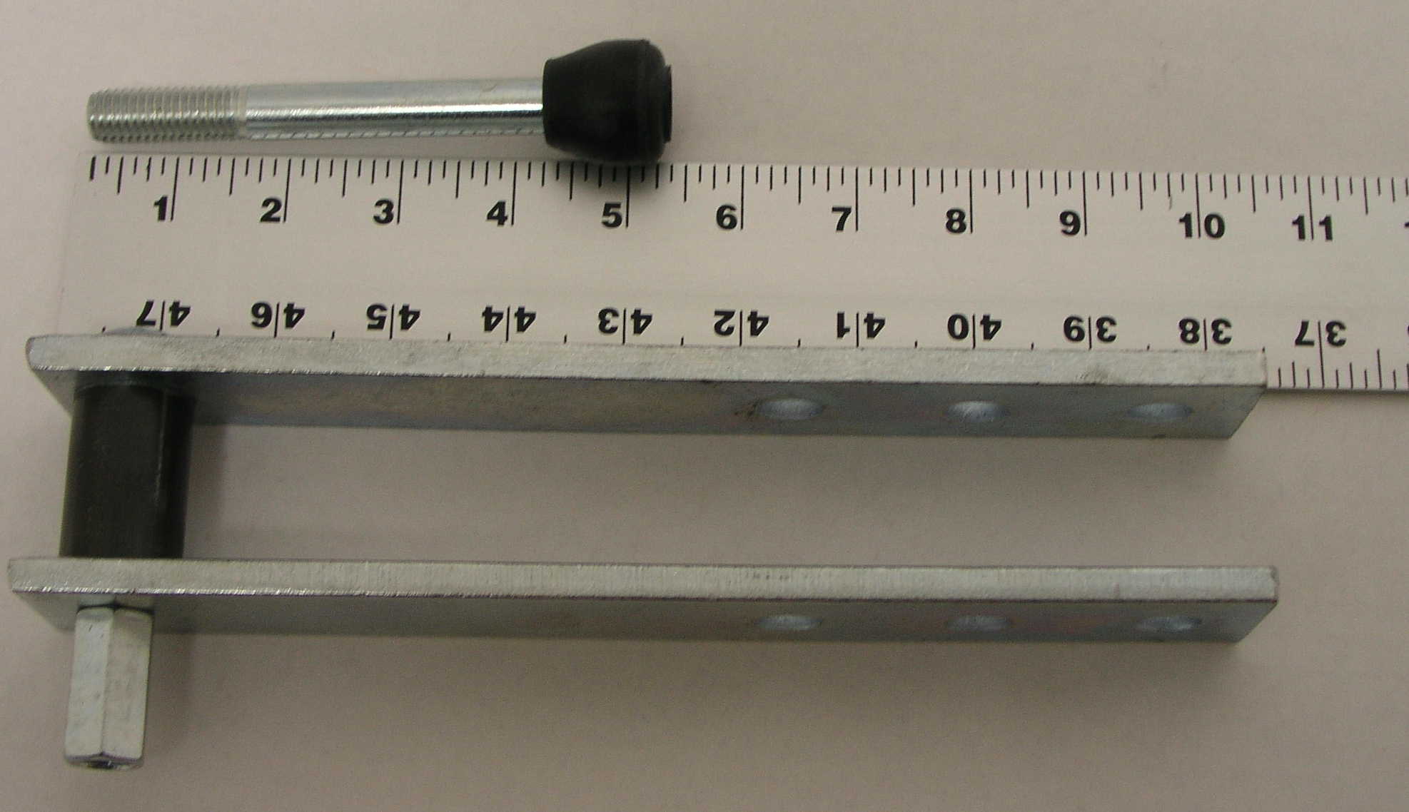 Secure Clutch and Brake Pedal Lock pictured against ruler for physical reference
of overall dimensions
Secure Clutch and Brake Pedal Lock pictured against ruler for physical reference
of overall dimensions
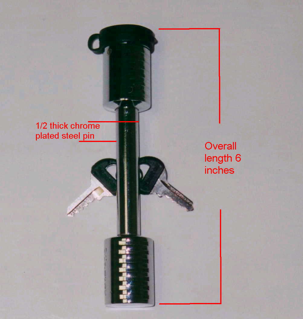 Lock assembly (physical dimensions)
 Another
view of the Secure Clutch and Brake Pedal Lock detailing the relative spacing of
the holes for securing the locking bolt. Using the mounting hole closest to the
pedal insures the least amount of movement of the assembly and provides a secure
locking of both the clutch and brake pedal
Another
view of the Secure Clutch and Brake Pedal Lock detailing the relative spacing of
the holes for securing the locking bolt. Using the mounting hole closest to the
pedal insures the least amount of movement of the assembly and provides a secure
locking of both the clutch and brake pedal
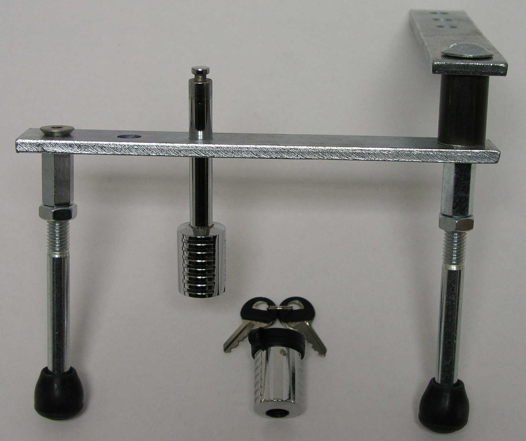 Secure
Clutch and Brake Pedal Lock Assembled and in the open position. This image shows the adjusting legs
attached to the coupling nut with the 2 jam nuts installed. The adjusting legs
are set so that the lower arm rests against the bottom of the vehicles
clutch and brake pedals. Note: the provided adjusting legs are 6 inches in
length, designed to fit most vehicles. If this does not meet your vehicles
requirements, simple remove the rubber end caps and replace with two 1/2 inch-13
bolts of the correct length, and replace the rubber ends.
Secure
Clutch and Brake Pedal Lock Assembled and in the open position. This image shows the adjusting legs
attached to the coupling nut with the 2 jam nuts installed. The adjusting legs
are set so that the lower arm rests against the bottom of the vehicles
clutch and brake pedals. Note: the provided adjusting legs are 6 inches in
length, designed to fit most vehicles. If this does not meet your vehicles
requirements, simple remove the rubber end caps and replace with two 1/2 inch-13
bolts of the correct length, and replace the rubber ends.
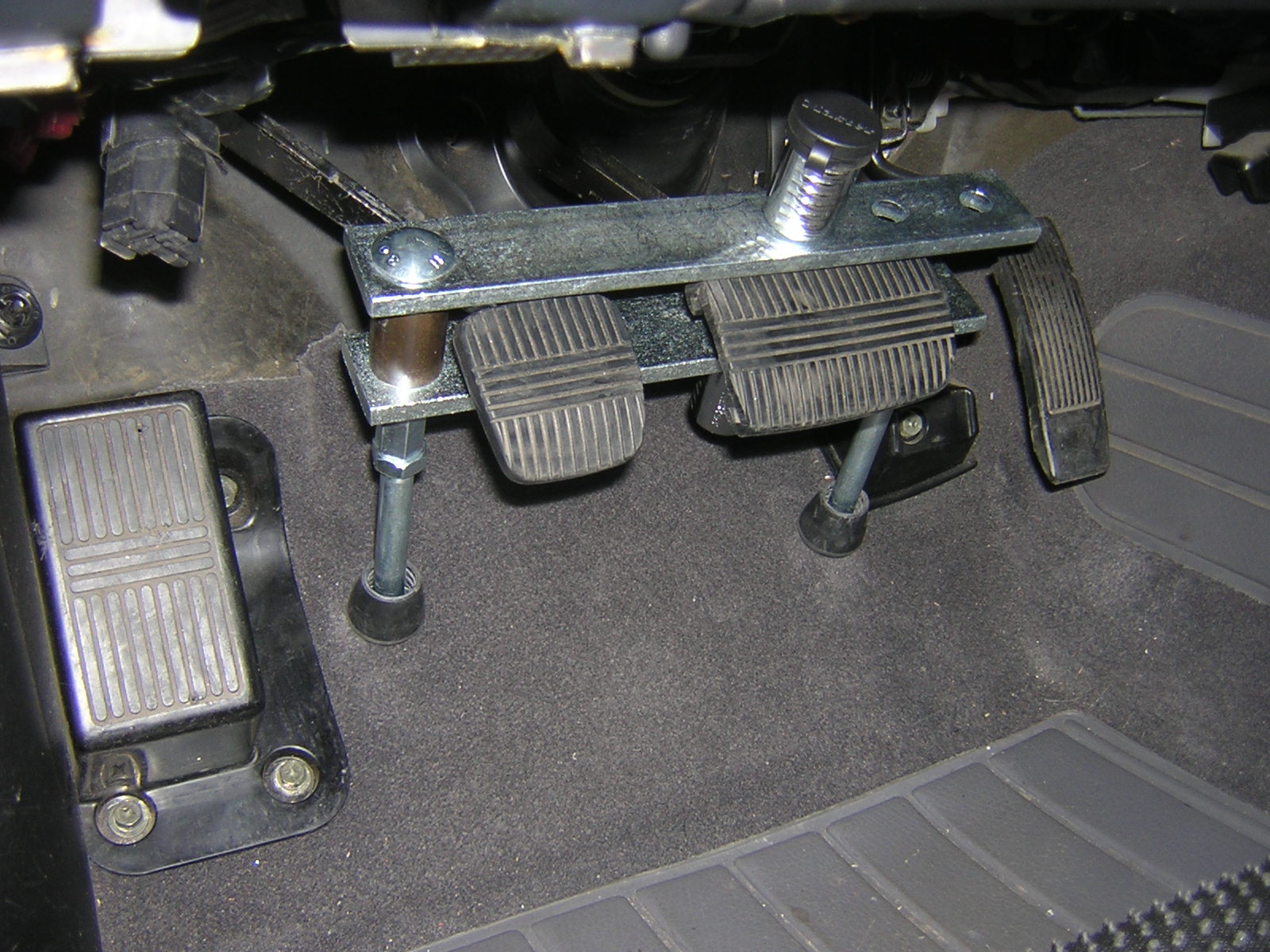 Image of the Secure Clutch and Brake Pedal Lock installed on a 1997 Nissan 240
SX. Image provided by one of our customers.
Image of the Secure Clutch and Brake Pedal Lock installed on a 1997 Nissan 240
SX. Image provided by one of our customers.
If you have any
questions at all please email us at
Simjack@optonline.net or you can call us at 888-7SIMJACK (888-774-6522)
Please note: Due to the volume of calls we receive we cannot always answer your
call. Please leave your name, number and a brief message and we will return your
call promptly.
Click here to return to our
Home Page